Automated Welding: Processes, Working Principles, and Automation Challenges
Automated welding has become an essential manufacturing technology for companies seeking higher productivity, consistent weld quality, and more efficient production processes. From robotic MIG welding in automotive factories to CNC laser welding for precision metal components, modern welding automation can be applied to a wide range of materials, product geometries, and industrial applications.
However, not all welding processes are equally easy to automate. Some can be integrated into a production line with relatively simple motion control and fixed process parameters. Others require advanced joint tracking, precise fixture design, real-time process monitoring, or specialized equipment to maintain stable welding conditions.This means for manufacturers, the key question is not simply whether a welding process can be automated. It is whether the process can be automated reliably, economically, and consistently for a specific product.
This article explains the main automated welding processes, their working principles, their advantages and limitations, and the technical challenges involved in integrating them into automated manufacturing systems. It also compares dedicated automatic welding machines, CNC welding platforms, and robotic welding systems to help manufacturers identify the most suitable solution.
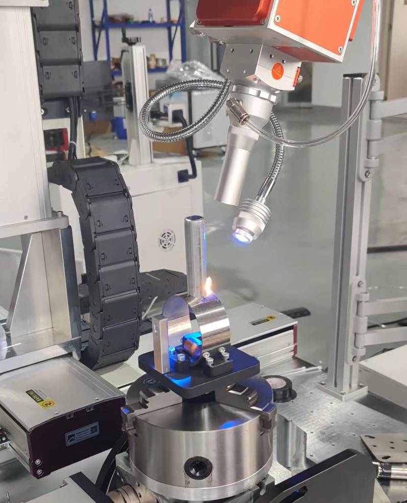
Fully automatic laser welding
What Is Automated Welding?
Automated welding is a process in which a welding machine automatically performs welding operations according to a pre-programmed path and set of welding parameters. Instead of manually controlling the welding head and its movement direction, the operator programs the system in advance, and the machine automatically completes the welding process.
A typical automated welding system consists of a welding source, a welding head or torch, a motion control system, and a programmable controller such as a CNC system. Depending on the welding process, the system can also control laser power, welding current, travel speed, wire feeding, and other process parameters.
After the workpiece is positioned and the program is started, the system automatically moves the welding head along the programmed path and performs the welding operation. This reduces the need for continuous manual intervention and helps achieve consistent welding results in repetitive production.
How Does Automated Welding Work?
The automated welding process typically involves four steps:
(1)Programming: The operator sets the welding path, movement coordinates, welding sequence, speed, and relevant process parameters.
(2)Workpiece positioning: The workpiece is placed and secured in the appropriate fixture to ensure correct alignment.
(3)Automatic execution: Once the program starts, the controller coordinates the movement system and welding source according to the programmed instructions.
(4)Welding completion: The welding head follows the programmed trajectory and completes the welding operation without the operator manually controlling its movement.
Automated welding can be implemented using different motion systems, including CNC platforms, dedicated automatic welding machines, and industrial robots. Robotic welding is one form of automated welding, using a programmed robot to move the welding torch or laser head along the required welding path.
The effectiveness of automated welding depends on accurate programming, stable workpiece positioning, consistent joint geometry, and appropriate welding parameters. For applications where the actual weld seam may deviate from the programmed path, sensors or seam-tracking systems can be added to improve positioning accuracy.
Which Welding Processes Can Be Automated?
Most established welding processes can be automated under suitable conditions. The main differences lie in their process characteristics, motion requirements, sensitivity to workpiece variation, and integration complexity.
The following table provides a general comparison.
| Welding process | Automation potential | Common automation methods | Main challenges |
|---|---|---|---|
| MIG/MAG welding | High | Welding robots, CNC systems, gantry machines | Joint tracking, arc stability, wire feeding, spatter |
| TIG welding | High for suitable applications | CNC platforms, robots, orbital welding systems | Heat input, molten-pool control, filler wire coordination |
| Laser welding | High for suitable applications | CNC platforms, robots, dedicated machines | Joint gap, focal position, seam location, laser safety |
| Resistance spot welding | Very high for repetitive production | Fixed machines, robotic spot welding cells | Electrode wear, contact conditions, current and force control |
| Plasma arc welding | Moderate to high | Dedicated machines, CNC systems, robots | Torch distance, gas flow, nozzle condition |
| Submerged arc welding | Very high for suitable long seams | Welding tractors, gantry systems, column-and-boom equipment | Welding position, flux handling, joint preparation |
| Friction stir welding | High for suitable product geometries | CNC machines, dedicated equipment, selected robotic systems | Machine stiffness, axial force, clamping |
| Laser cladding | Moderate to high | CNC systems, robots, rotary-axis platforms | Powder or wire delivery, dilution, layer geometry |
| Shielded metal arc welding | More limited for continuous production | Specialized mechanized equipment | Electrode replacement, slag removal, process continuity |
| Plastic laser welding | High for compatible assemblies | Dedicated machines, CNC platforms, robots | Material compatibility, interface contact, clamping |
The automation potential shown here is not an absolute ranking. A process that is highly suitable for one application may be impractical for another.
For example, resistance spot welding is exceptionally effective for repetitive overlapping sheet-metal joints, but it is not a direct replacement for continuous seam welding. Laser welding offers precise energy delivery, but it may require tighter joint fit-up than some wire-fed arc welding applications.
The correct choice must consider the complete joining operation rather than the welding process alone.
How Different Automated Welding Processes Work
Automated MIG/MAG Welding
MIG/MAG welding, also known as gas metal arc welding (GMAW), uses an electric arc between a continuously fed consumable wire electrode and the workpiece.The arc melts the wire and the base material to form a joint. Shielding gas protects the arc and molten weld pool from atmospheric contamination.
In MIG welding, inert shielding gases are used. MAG welding uses active shielding gases or gas mixtures. In industrial applications, the two processes are often discussed together because they share similar equipment and automation principles.
Working Principle of Automated MIG/MAG Welding
A typical automated MIG/MAG system includes:
- A welding power source
- A wire feeding system
- A welding torch
- A shielding gas supply
- A motion system
- A programmable controller
- Fixtures and workholding equipment
During welding, the wire feeder continuously supplies electrode wire while the power source maintains the required electrical conditions. The motion system moves the torch along the programmed seam.
The controller coordinates current, voltage, wire feed speed, travel speed, torch angle, and shielding gas delivery. Depending on the application, the system may also control weaving motion, welding starts and stops, and the sequence of multiple weld passes.
The torch can be mounted on an industrial robot, a CNC gantry, a welding carriage, or a dedicated automatic welding machine.
Why Is MIG/MAG Welding Suitable for Automation?
Continuous wire feeding is one of the main advantages of MIG/MAG welding. Unlike processes that require frequent manual electrode replacement, it can support long, uninterrupted welding cycles.Modern welding power sources also provide controlled transfer modes and programmable process parameters, making the process suitable for repetitive industrial production.
Common applications include automotive components, machinery frames, agricultural equipment, steel structures, metal cabinets, and general metal fabrication.
However, automated MIG/MAG welding still depends on joint consistency. If the actual weld seam differs significantly from the programmed path, the system may produce an incorrectly positioned weld or an unacceptable weld profile.
Touch sensing, arc sensing, and laser seam tracking can help compensate for certain variations, depending on the joint and system configuration.
Main advantage: High productivity and mature automation technology.
Main limitation: Joint variation, arc stability, spatter, and the need to coordinate several process variables.
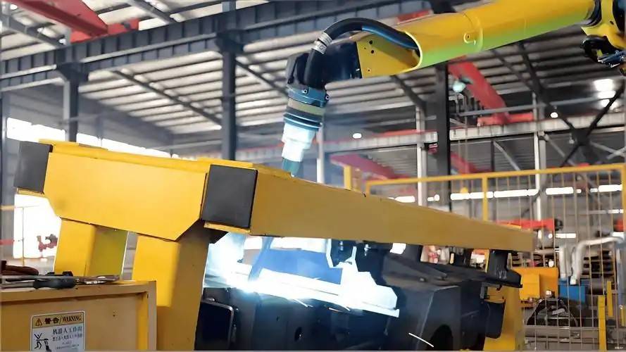
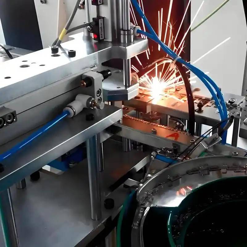
Automatic MIG Welding
Automated TIG Welding
TIG welding, also known as gas tungsten arc welding (GTAW), uses a non-consumable tungsten electrode to generate an electric arc. Shielding gas protects the electrode and molten weld pool.Filler wire may be added when required by the joint design and welding procedure.
Working Principle of Automated TIG Welding
An automated TIG welding system controls the relative movement between the torch and workpiece while maintaining the required electrical and thermal conditions.
The main parameters may include welding current, pulse settings, travel speed, arc length, shielding gas flow, and filler wire feed rate.
For circular pipes and tubes, orbital welding systems can move the torch around the joint or coordinate the movement of the torch and workpiece. CNC systems and robots can be used for more complex geometries.
Why Can TIG Welding Be More Challenging to Automate?
TIG welding offers precise heat control and can produce clean welds with good appearance. It is particularly useful for stainless steel tubing, precision components, thin materials, and applications requiring controlled heat input.
However, the molten pool can be sensitive to changes in travel speed, torch position, joint gap, and heat input. When filler wire is used, its delivery must also be coordinated with the welding motion and molten-pool behavior.
For thin materials, excessive heat input may cause distortion or burn-through. For thicker sections, the required penetration and number of welding passes must be established through process development.
Automated TIG welding therefore requires a carefully developed welding procedure, repeatable workholding, and appropriate control of torch position and process parameters.
Main advantage: Precise heat control and high-quality welds.
Main limitation: Process sensitivity and potentially lower production speed than higher-deposition alternatives.
Automated Laser Welding
Laser welding uses a concentrated laser beam to heat and melt material at the joint. The beam can be delivered through focusing optics and directed along a programmed path by CNC equipment, a robotic arm, or a dedicated motion system.
Compared with many conventional arc welding processes, laser welding can concentrate energy into a relatively small area. Under suitable conditions, this can reduce the overall heat input and help limit distortion.
Working Principle of Automated Laser Welding
A typical system includes a laser source, welding head, focusing optics, motion platform, controller, cooling system, and appropriate safety equipment.
During welding, the controller coordinates laser output with the movement of the welding head or workpiece.It can operate in different modes depending on power density and process conditions.
In conduction-mode welding, energy is absorbed near the surface, melting the material without establishing a deep keyhole.
In keyhole-mode welding, the concentrated energy creates a vapor cavity in the molten material. This can enable deeper penetration than conduction-mode welding under suitable conditions.
The appropriate operating mode depends on the material, thickness, laser characteristics, joint geometry, and required weld properties.
Why Is Laser Welding Suitable for Automation?
Laser welding has several characteristics that support automated production.
First, the laser beam provides non-contact energy delivery. The welding head does not need to press an electrode against the joint.
Second, laser power, travel speed, and focal position can be controlled through the system. This supports repeatable process execution once a suitable welding procedure has been established.
Third, the laser head can be integrated into different motion platforms. A CNC laser welding machine may be suitable for defined paths and repeatable workpieces, while a robot can provide greater flexibility for complex three-dimensional components.
Common applications include stainless steel products, battery components, electronic housings, automotive parts, sheet-metal assemblies, and precision metal components.
Main advantage: Concentrated energy input, high potential welding speed, and flexible integration with CNC and robotic systems.
Main limitation: Sensitivity to joint fit-up and process conditions in many configurations.
Automated Resistance Spot Welding
Resistance spot welding joins overlapping metal sheets by passing electrical current through the contact region while applying pressure through electrodes.The electrical resistance of the joint generates heat, producing a localized molten region known as a weld nugget. The electrodes maintain pressure during the welding cycle and help the joint consolidate as it cools.Unlike continuous seam welding, resistance spot welding generally creates a series of individual welding points.
Working Principle of Automated Spot Welding
A typical system controls:
(1)Electrode positioning
(2)Electrode force
(3)Welding current
(4)Current duration
(5)Hold time
(6)Electrode release
The electrodes close on the workpieces and apply force. The system then delivers current for a specified duration before maintaining pressure for the required hold time.The equipment may be a fixed spot welding machine or a robot-mounted welding gun integrated into a production cell.
Why Is Spot Welding Highly Suitable for Automation?
Resistance spot welding has a relatively defined cycle and is particularly effective when the parts have consistent dimensions and repeatable joint positions.
It is widely used in automotive body manufacturing, sheet-metal assemblies, appliances, and other high-volume products.
The main automation challenges involve electrode wear, changes in contact resistance, material stack-up, surface condition, and electrical shunting between nearby weld locations.
Electrode dressing, force monitoring, current monitoring, and periodic weld-quality verification can help maintain production consistency.
Main advantage: Fast, repeatable production of suitable overlapping sheet-metal joints.
Main limitation: Restricted joint configurations and the need to manage electrode condition and contact quality.
Automated Plasma Arc Welding
Plasma arc welding (PAW) is an arc welding process that constricts the arc through a specially designed nozzle. This produces a concentrated heat source with different characteristics from a conventional TIG arc.
Working Principle of Automated Plasma Welding
A plasma welding system coordinates the welding power source, torch movement, plasma gas, shielding gas, and process timing.Depending on the configuration, the controller adjusts current, travel speed, gas flow, torch-to-work distance, and other parameters.Dedicated automatic machines are suitable for repeatable components, while CNC systems or robots can be used for more complex paths.
Automation Advantages and Limitations
Plasma arc welding can provide a concentrated and controllable heat source for selected precision and production applications.However, its performance depends on torch position, gas flow, nozzle condition, and the selected operating mode. Joint preparation and process stability remain important.It is therefore a useful option for specific applications rather than a universal replacement for MIG/MAG, TIG, or laser welding.
Main advantage: A concentrated arc and good process control in suitable applications.
Main limitation: Specialized process requirements and sensitivity to torch and nozzle conditions.
Automated Submerged Arc Welding
Submerged arc welding (SAW) uses an electric arc between a continuously fed wire electrode and the workpiece. The arc and molten weld pool are covered by granular flux during the process.The flux protects the weld region and contributes to the process characteristics. SAW is widely used for long weld seams and relatively thick steel components.
Working Principle of Automated SAW
A typical system includes a power source, wire feeder, welding head, flux delivery and recovery equipment, motion system, and workpiece positioning equipment.The welding head may be mounted on a welding tractor, gantry, or column-and-boom system.During operation, the system coordinates wire feed, electrical parameters, travel speed, and flux delivery while following the planned weld path.
Why Is SAW Suitable for Automation?
Submerged arc welding is particularly effective for long, continuous welds on large components.Once the joint is prepared and the process parameters are established, the equipment can maintain a stable welding cycle over extended seams.
Common applications include pressure vessels, storage tanks, large pipes, structural steel, and heavy fabrication.
However, SAW is less convenient for short, intricate seams or joints that require many changes in welding position. Flux handling and joint preparation must also be considered when designing the automated system.
Main advantage: High deposition capability for suitable long seams and thick sections.
Main limitation: Restricted application geometry and the need for flux management.
Automated Friction Stir Welding
Friction stir welding (FSW) is a solid-state joining process. Instead of melting the base materials, it uses a rotating tool to generate frictional heat and mechanically stir softened material along the joint.The tool travels along the joint while applying controlled mechanical pressure. The softened material flows around the tool and consolidates behind it to form the joint.
Working Principle of Automated FSW
An automated FSW system controls tool rotation, travel speed, plunge depth, tool position, and axial force or position, depending on the machine and control strategy.
Because the process involves substantial mechanical loads, the machine structure and workholding system must provide sufficient stiffness.
CNC machines and dedicated FSW equipment are common solutions. Robotic systems can also be used in suitable applications, provided that their stiffness, force capacity, positioning performance, and process requirements are appropriate.
Why Is FSW Suitable for Automation?
Once the tool, joint, and process parameters have been established, the system can follow a repeatable path without relying on a conventional molten weld pool.
FSW is used for selected aluminum structures, transportation components, panels, and other applications where solid-state joining provides advantages.
The main challenges include tool wear, force control, rigid clamping, joint access, and the treatment of entry and exit regions.
Main advantage: Solid-state joining can offer useful metallurgical benefits for suitable materials and applications.
Main limitation: High mechanical loads and demanding fixture and machine-stiffness requirements.
Automated Laser Cladding
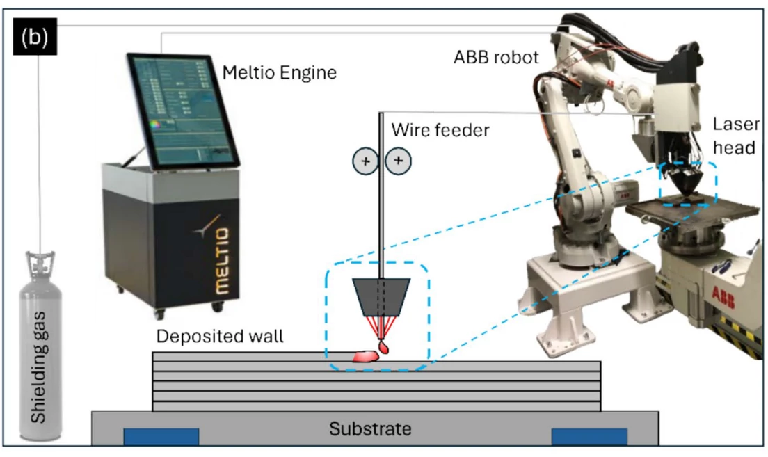
Laser cladding is a surface engineering process in which a laser melts a controlled region of the substrate while additional material is supplied in powder or wire form.The added material and a limited amount of substrate form a metallurgically bonded layer. The objective is generally to improve surface properties or restore a component rather than join two separate parts.
Although laser cladding differs from conventional fusion welding, it shares several automation technologies with laser welding, including controlled motion, laser power regulation, material feeding, and process monitoring.
Working Principle of Automated Laser Cladding
A typical system includes a laser source, cladding head, powder or wire delivery system, motion platform, shielding arrangement, and controller.
In powder-fed cladding, powder is transported to the interaction zone and incorporated into the melt pool. In wire-fed cladding, wire is delivered into the molten region.
The motion system controls the processing path, track overlap, layer sequence, and relative position of the head and component.CNC systems, rotary-axis platforms, and industrial robots can be used depending on the geometry and working range required.
Automation Challenges in Laser Cladding
Laser cladding requires coordinated control of laser power, travel speed, powder or wire feed rate, stand-off distance, track overlap, and shielding conditions.The quality of the deposited layer also depends on substrate preparation, material compatibility, dilution, porosity, cracking risk, and the geometry of the finished surface.
Automation helps maintain repeatable motion and material delivery, but a programmed path alone cannot guarantee a defect-free coating.
Main advantage: Controlled deposition for surface restoration and functional coatings.
Main limitation: Complex interactions between heat input, material delivery, melt-pool behavior, and final layer properties.
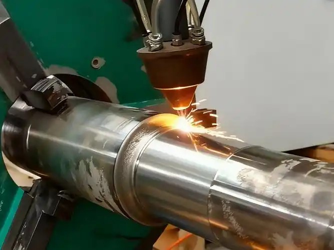
Laser Cladding Process
Automated Shielded Metal Arc Welding
Shielded metal arc welding (SMAW), commonly called stick welding, uses a flux-coated consumable electrode to generate an arc. The coating contributes to shielding and slag formation.The process is widely used for construction, maintenance, field work, and repair.
Why Is Stick Welding More Difficult to Automate?
The main challenge is process continuity.The electrode becomes shorter during welding and must eventually be replaced. Slag may also need to be removed between passes, depending on the welding procedure.These requirements make continuous automated production more complicated than processes using continuous wire feeding.
Specialized mechanized equipment can automate certain repetitive stick welding operations, but the process is often less attractive for high-volume automated manufacturing.Where the material, joint configuration, and quality requirements permit, MIG/MAG, submerged arc welding, or another process may provide a more convenient route to continuous production.
Main advantage: Versatility in maintenance, repair, and field applications.
Main limitation: Consumable replacement and interruption of the welding cycle.
Why Are Some Welding Processes Easier to Automate Than Others?
The difficulty of welding automation is not determined by the energy source alone. It depends on the interaction between the welding process, workpiece geometry, joint consistency, motion requirements, and production workflow.
Continuous Processes vs. Intermittent Processes
Processes using continuous wire feeding, such as MIG/MAG welding and submerged arc welding, can support long welding cycles without frequent replacement of the primary consumable.Resistance spot welding also lends itself to automation because it follows a repeatable cycle at predefined locations.
By comparison, stick welding requires electrode replacement and may require slag removal. These interruptions increase the complexity of continuous production.
However, continuous operation is only one factor. A continuous welding process may still require complex sensing and motion control if the joint geometry is variable.
Fixed Weld Locations vs. Variable Weld Paths
A machine that repeatedly welds the same circular component may only need one or two coordinated axes.While a component with multiple weld seams at different angles may require a multi-axis CNC system, a workpiece positioner, or a robot.The more complex the geometry, the more important tool orientation, reach, collision avoidance, and accessibility become.
This is why a dedicated machine can outperform a robot in a stable, repetitive application, while a robot may be more suitable for a diverse product family.
Joint Fit-Up and Process Tolerance
Different processes tolerate different amounts of joint variation.Some wire-fed arc welding applications can accommodate a certain range of gaps through suitable filler deposition and qualified procedures. Many laser welding configurations, particularly those without filler material, are more sensitive to joint gaps and seam position.
This does not mean that laser welding cannot handle variable joints. Filler wire, joint redesign, seam tracking, and adaptive process strategies can extend its application range. However, these measures add engineering and integration requirements.
The important question is whether the complete system can maintain the required joint quality under the expected range of production variation.
Heat Input and Process Stability
Welding processes differ in how energy is delivered and how the joint forms.
In arc welding, the system must maintain suitable electrical conditions and control torch movement, shielding, and filler delivery.
In laser welding, the system must coordinate the beam position, focal conditions, power, and travel speed.
In resistance spot welding, electrode force and electrical contact conditions strongly influence heat generation at the joint.
In friction stir welding, mechanical force, tool rotation, and travel speed must be coordinated.
Automation must therefore be designed around the physical mechanism of the selected process, not simply around the movement of the welding tool.
Consumables, Tool Wear, and Maintenance
Automated welding does not eliminate consumable wear.Wire feeders, welding torches, contact tips, electrodes, laser optics, powder delivery systems, and friction stir tools all require appropriate inspection and maintenance.The maintenance strategy affects the real production capacity of the system. A machine with a short welding cycle may still have poor overall availability if consumables require frequent intervention or if access for maintenance is difficult.
For this reason, maintenance access and consumable management should be considered during system design.
How Sensors and Adaptive Control Improve Automated Welding
A programmed welding path works well when the workpiece is consistent and correctly positioned. When variation cannot be eliminated through manufacturing and fixturing alone, sensing may be needed.Sensors can help locate the joint, detect the actual part position, monitor selected process conditions, or provide information for quality assessment.However, monitoring, correction, and adaptive control are different functions.
Vision Systems and Joint Location
A vision system can identify a component or estimate the location of a joint before welding.
For example, a camera may determine the position of a workpiece relative to the machine coordinate system. The controller can then adjust the planned trajectory to account for the measured position.This approach is useful when parts vary slightly in position but remain within the sensing system’s operating range.
The accuracy depends on factors such as lighting, surface condition, camera calibration, viewing angle, and the geometry of the feature being detected.
Laser Seam Tracking
Laser seam tracking uses optical measurements to determine the location or profile of a joint.Depending on the system, the sensor may measure the joint before welding or provide information during the welding operation.The controller can use the measured data to correct the welding path or adjust the relative position of the tool and workpiece.
Seam tracking is especially useful when the actual joint position differs from the nominal CAD or programmed path.However, the sensor must be compatible with the material surface, joint geometry, process environment, and required measurement accuracy. A sensor cannot reliably compensate for every type of joint variation.
Touch Sensing and Arc Sensing
Touch sensing uses physical contact or an electrical signal to identify a reference position before welding. It is useful in selected applications where the joint can be located through controlled probing.
Arc sensing uses changes in welding signals associated with the torch’s position relative to the joint. In suitable arc welding configurations, these signals can help guide the welding torch along the seam.
The effectiveness of either method depends on the process, joint type, and operating conditions.
Process Monitoring
Process monitoring records or evaluates signals associated with welding.Depending on the system, these may include welding current, voltage, laser output, reflected optical signals, temperature, or other process measurements.Monitoring can help identify abnormal conditions, document the production process, and support troubleshooting.
However, detecting an abnormal signal is not the same as proving that a weld is defective. The relationship between the measured signal and the actual joint quality must be established for the specific application.
What Is Adaptive Welding Control?
Adaptive welding control uses feedback to adjust selected process variables or motion parameters in response to measured conditions.
For example, a system may correct the path after locating the actual seam. In a more advanced application, a validated control strategy may adjust selected parameters to compensate for changing process conditions.Adaptive control requires more than adding a sensor. The system needs a defined measurement method, a control strategy, acceptable adjustment limits, and evidence that the correction improves the required welding outcome.A practical progression is to establish a stable welding procedure first, then add sensing to address a clearly identified source of variation.
Common Challenges in Welding Automation
Even when the welding process itself is suitable for automation, the complete system must overcome several practical challenges.
Inconsistent Joint Position
If a workpiece is incorrectly positioned, a programmed path may no longer align with the actual joint.
Possible solutions include improving fixture accuracy, tightening upstream manufacturing tolerances, using touch sensing, or integrating vision and seam-tracking systems.The most appropriate approach depends on the magnitude and type of variation. Improving part consistency may be simpler and more reliable than relying entirely on sensors.
Variable Joint Gaps
Joint gaps affect how heat is distributed and how molten material fills the joint.
Laser welding configurations without filler material can be particularly sensitive to gaps. Wire-fed processes may accommodate certain variations more readily, but they also have practical limits.Countermeasures may include improved part tolerances, a revised joint design, suitable filler material, or a qualified adaptive welding procedure.
Complex Three-Dimensional Geometry
A robot may physically reach a joint but still be unable to approach it at the correct angle or maintain the required tool orientation.
The system must consider reach, torch access, cable routing, collision avoidance, and process requirements.Simulation, fixture planning, and early evaluation of tool accessibility can reduce integration problems.
Heat Distortion and Workpiece Movement
Welding introduces heat and residual stresses. Thin components may deform, while larger assemblies can shift as welding progresses.
Distortion can affect the position of later seams even if the original workpiece was located accurately.Possible solutions include fixture improvements, optimized welding sequences, suitable heat input, tack welding, and measurement or tracking where justified.
Consumables and Maintenance
Automatic welding systems still require maintenance.
Wire-fed processes require attention to wire delivery and torch condition. Resistance spot welding electrodes wear and may need dressing or replacement. Laser systems require suitable protection and inspection of optical components. Powder-fed cladding systems require stable material delivery and appropriate handling.
Maintenance access, consumable replacement, and fault recovery should be included in the production design.
Loading, Unloading, and Inspection
An automatic welding cycle does not necessarily mean that the entire production process is automated.If an operator must manually load each part, position it, clamp it, unload it, and inspect it, those tasks can limit the overall production rate.
Depending on the application, automation may extend to part identification, robotic loading, clamping verification, post-weld inspection, and transfer to the next manufacturing operation.
The additional equipment and integration costs should be evaluated against the expected improvement in production throughput and consistency.
Automated Welding vs. Intelligent Welding
Basic automated welding follows a programmed sequence using predefined process parameters. Intelligent or adaptive welding uses additional information from sensors or process feedback to respond to changing conditions.
For example, a basic CNC welding machine may follow the same path for every component. A sensor-assisted system may locate the actual seam and adjust the programmed path before welding.A more advanced system may monitor process signals and use a validated feedback strategy to adjust selected parameters during operation.
It is important to distinguish three concepts.
Programmed automation: The system executes predefined motion and process parameters.
Sensor-assisted automation: The system measures the workpiece or process and uses the information to make defined corrections or verify conditions.
Adaptive process control: The system uses feedback to adjust relevant process variables according to a validated control strategy.
These capabilities can be combined, but not every application requires the most advanced configuration.A stable, high-volume product may achieve excellent results with a well-designed fixture and a repeatable program. A high-value component with variable joint conditions may justify additional sensing and process monitoring.
The goal is to address actual sources of variation rather than add technology without a clear production benefit.
How to Choose the Right Automated Welding Solution
Selecting an automated welding system should begin with the product and its manufacturing requirements, not with the assumption that a particular machine type is always the best option.
Step 1: Identify the Material and Thickness
Material composition, thickness, thermal conductivity, surface condition, and material combinations all influence process selection.Stainless steel, carbon steel, aluminum, copper, and engineering plastics have different thermal and joining characteristics.
The preferred process should be evaluated against the actual material combination and required joint performance.
Step 2: Define the Joint Type
Determine whether the application requires a butt joint, lap joint, fillet weld, circular seam, pipe joint, or another configuration.Consider required penetration, allowable joint gap, tool accessibility, and whether filler material is necessary.Joint design has a direct effect on the feasibility and cost of automation.
Step 3: Evaluate Workpiece Geometry
Identify the number of weld seams, their locations, the required tool angles, and whether the workpiece needs to rotate or change orientation.
Straight or circular seams may suit dedicated machines. More complex three-dimensional components may benefit from CNC multi-axis equipment or robotics.
Step 4: Estimate Production Volume and Product Variation
High-volume production with a stable design may justify dedicated automation.
A product family with several variants may benefit from programmable CNC equipment or a robotic system, depending on the complexity of the differences.
For small production batches, the cost of fixtures, programming, changeover, and operator training must be considered alongside welding cycle time.
Step 5: Define Quality Requirements
Specify the required penetration, weld geometry, strength, leak tightness, appearance, distortion limits, and inspection criteria.
Determine whether the application requires process monitoring, dimensional inspection, destructive testing, or nondestructive testing.
The quality requirements should guide the selection of the welding process and the level of monitoring.
Step 6: Evaluate the Complete Production Cycle
Consider loading, positioning, clamping, welding, inspection, unloading, maintenance, and fault recovery.
A short welding time does not necessarily produce high overall productivity if the machine spends significant time waiting for parts or changing fixtures.
Cycle time should be evaluated across the complete production sequence.
Step 7: Conduct Representative Welding Trials
Before committing to a production system, test representative workpieces under realistic conditions.
The trials should establish whether the selected process can meet the required quality, cycle time, and repeatability targets.
Depending on the application, the project may also require fixture validation, process qualification, safety assessment, and a plan for production monitoring.
Common Applications of Automated Welding
Automated welding is used across many manufacturing industries. The most suitable process depends on the product, joint design, production requirements, and applicable quality standards.
| Industry or application | Common automation approaches | Key requirements |
|---|---|---|
| Automotive manufacturing | MIG/MAG robots, resistance spot welding, laser welding | High throughput, repeatability, production-line integration |
| Sheet metal fabrication | MIG/MAG, TIG, laser welding, dedicated machines | Accurate fit-up, flexible production |
| Pipes and tubes | Orbital welding, rotary welding, CNC systems | Consistent circumferential joints and access |
| Stainless steel products | TIG, laser, MIG/MAG, CNC systems | Weld appearance, corrosion resistance, distortion control |
| Heavy steel fabrication | Submerged arc welding, mechanized arc welding, robotic MIG/MAG | Long seams, deposition rate, structural quality |
| Precision components | Laser welding, automated TIG, resistance welding | Controlled heat input and accurate positioning |
| Surface restoration | Laser cladding and mechanized overlay processes | Deposition consistency and surface properties |
| Automotive plastic assemblies | Plastic laser welding and dedicated joining systems | Material compatibility and interface contact |
| Medical and electronic components | Qualified laser, resistance, or specialized joining systems | Precision, traceability, and cleanliness where required |
These examples illustrate common applications rather than universal recommendations. Each project should be evaluated against its actual material, joint design, quality requirements, and manufacturing conditions.
Automated Welding Solutions from ZS Machinery
ZS Machinery specializes in automated laser welding solutions for batch production. Our main products include CNC laser welding machines and robotic laser welding systems, designed to help manufacturers improve welding efficiency, maintain consistent weld quality, and reduce dependence on manual welding operations.
For manufacturers producing the same or similar parts in batches, laser welding automation can provide a more controlled and repeatable production process. Once the welding path, motion sequence, and process parameters have been configured, the system can automatically perform the programmed welding operation with minimal manual intervention during each cycle.
The right solution depends on the workpiece geometry, welding path, production volume, and required level of flexibility. ZS Machinery focuses on matching the laser welding system to the actual production requirements rather than simply supplying a standard machine.
Contact ZS Machinery for Automated Laser Welding Solutions
Looking to automate your welding process for batch production? ZS Machinery provides CNC laser welding machines and robotic laser welding systems tailored to different workpiece geometries, welding requirements, and production goals.
Whether you need to automate repetitive welding paths, improve welding consistency, or develop a customized solution for complex workpieces, our team can help you evaluate your application and identify a suitable equipment configuration.
Contact ZS Machinery to discuss your laser welding project. To help us understand your requirements, please share the following information if available:
- Workpiece drawings, photos, or samples
- Material type and thickness
- Welding joint design and required welding positions
- Expected production volume and cycle time
- Current welding process and challenges
Based on your application, we can evaluate process feasibility, recommend a suitable CNC or robotic laser welding system, and discuss the next steps for sample testing and equipment configuration.
Contact us today to explore a customized automated laser welding solution for your production line.
Fiber Laser Welder: Types, Applications, Power Selection, and Automation Solutions